
"Throttle Controller for an Autonomous ATV - Air Ground project"
Field Robotics Center (Oct'18 - May'19)
Carnegie Mellon University, USA
Advisor - Prof. George Kantor
An UAV scans the entire terrain of interest that the ATV on ground can traverse, and sends an optimal path from its current location to the desired location. The ATV then executes the path with local planner, throttle controller and other software stacks - localization, vision, prediction.
My responsibilities - An Autonomous vehicle (Yamaha Viking ATV) needs to navigate and follow a path through a series of waypoints. Taking the surroundings into consideration, we want to control the throttle valve of the vehicle appropriately in order to track the path with the required velocity.
Initially, the system didn't have an automated throttle valve control, and so the task is to develop hardware (motors, communication, manufacture components to mount the motor) and software (control algorithms for throttle valve control) in ROS framework.

Choosing A Motor Actuator
The throttle valve was located in the vehicle by following the wire from the foot pedal to the throttle body. After removing the mount that was covering the throttle valve, a picture of the same has been attached below.

First, physically I checked how difficult it was to actuate the throttle valve by hand. It was quite difficult as the spring was strong providing a restoring torque. Hence I started searching for the right motor that can be used. A minimum of 0.6 N-m is required to actuate the throttle valve.
Dimensions were also a constraint. In the vehicle, the space provision available to mount the motor and support mounts for the same shouldn't exceed a maximum of 8 centimeter cube, approximately.
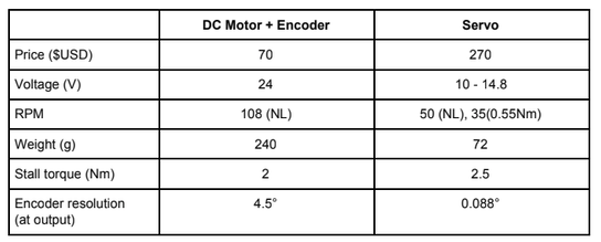
With two options for actuation in mind,
1. To use a Brushed DC motor along with an encoder,
2. To use a servo motor with encoder,
searched for different motors and chose one best & suitable available motor for each option
1. Brushed DC
2. Servo motor
With a comparison chart prepared, and analyzing the parameters, as the encoder resolution for Servo motor was better, I decided to go ahead with the Servo motor (Picture attached below - Dynamixel MX28T). As the encoder resolution is less, this means we can control the throttle valve angle more precisely which is exactly what we want.

CAD Design For Mounts
Used the following Solidworks design file of MX28T from GrabCad to design the mounts that fixes the position and connects this motor to the throttle body.

Throttle Valve Model
There are three torques acting on the throttle valve during its operation.
1. Torque applied by the motor for controlling the position
2. Restoring torque applied by the spring
3. Natural, unavoidable damping torque, due to friction and other parameters.
Theta - Angle of throttle valve
Ks - Spring constant
Kd - Viscous friction constant
Cs - Motor torque constant
J - Inertia of throttle valve
These three torques mentioned above, results in effective torque of the throttle valve and the angular acceleration is computed by dividing its Inertia J to the effective torque applied on the throttle valve as shown in this equation.

I designed a MATLAB Simulink model using the dynamics equation.

Testing The Dynamics Model With A Pid Controller (Sanity Check)
Tuned the PID block in Simulink for the dynamics model with a simple step input.
The throttle valve is expected to reach 90 degree angle in the test. The step input (shown in yellow) and the response (shown in blue)
The output scopes are also attached right below it.


Understanding The Local Planner
Out of interest, I went though the existing code-base from a third party to analyse the local planner used for the vehicle to track different waypoints. I went through the different files, back-tracked and prepared a chart that explains the local planner.
It was basically a standard Pure Pursuit trajectory tracking algorithm.

Hardware Connections To Operate And Play With The Motor
1. Firstly, I used the U2D2 device which came along with the motor and connected it to the laptop (U2D2 is a USB communication converter that enables to control and operate Dynamixel with PC - It doesn't power the motor and so I used a separate voltage supply)
2. Then, I connected the 3pin TTL to U2D2 and connected the other end to Dynamixel motor MX28 3 pin slot to read data from the motor and get feedback. (Image on the right)


3. The other side of the Dynamixel MX28 has a 3 pin slot. The +ve and -ve (2nd pin and 1st pin respectively as per the documentation) is connected to the power supply, 12V DC Regulated power supply. Black and yellow wires are negative and positive supply respectively.


Getting Feedback From Dynamixel MX28 Servo Motor
Firstly, I installed R+ Manager software provided by Robotis to configure and analyse the Dynamixel motor.
A separate DC regulated 12V power supply was given to the motor.
Once that is done, firmware update was done to make sure my software was upto date. This can be done from the main page of R+ Manager software GUI directly.
I then calibrated the Dynamixel motor, steps of 90 degree positions were chosen as per the procedure showed in the documentation, it takes the encoder counts into consideration.
Steps done to set up the motor and to analyse its parameters (Video attached below)
1. Hardware connections as mentioned in previous section
2. Powered the motor with 12V supply
3. Chose 'Update and Test' option in R+ Manager
4. Chose the COM port in which my U2D2 USB cable was connected, COM3 port in my case
5. Then chose a baud rate (57600 bps is recommended as per documentation) for searching
6. Now the device was detected, with the version details of the firmware and motor
7. The communication then began, blue and green LEDs glow back and forth in the U2D2. This can also be checked by noticing the TX and RX columns flashing in the bar with green stripes in GUI (Named as Control table in the interface)
Now that our communication is established, the GUI (Control table) has several address numbers, P,I,D gains, position encoder ticks, time ticks, moving status of the motor and lots more. Each value numerically tells us about the current status of the motor and its configuration which can also be changed in real-time.
As I rotated the motor manually, it was seen that the moving status changed to 1 from 0, current position ticks and a graphic display of the motor with its current angular position (Figure attached above). Hence, over the entire range of parameters, we have feedback of all parameters through the GUI that we can read realtime.
Giving Position Commands to Servo Motor - Pid Control
Now that we have feedback of the motor configuration, parameters, etc. in our system, the next step is to give position commands and look for motor response.
The R+ Manager software GUI has an inbuilt PID parameter tuning block. The proportional gain of zero will not rotate the servo to the commanded position at all (obviously), it showed 'Following error'. It has to be tuned, a proportional around the range of 700 to 900 had to be used to make the motor follow my commands.
With the Torque enable turned Off, and choosing address 116 (Address number for commanding goal position) in the GUI, by simply clicking on the angle we wish to position the motor, you can see that the motor changes its angular position in real time.
Steps To Command An Angular Position For The Motor
1. Steps 1 to 7 as same as the previous section
2. Went to address 116 in control table and there is a green (Motor angular positions) towards the right side of the GUI with a red arrow which is the marker for current position. Click anywhere. Video below.
Integrating The Motor In ROS Framework
Created a workspace and built the packages from Dynamixel's Github
After catkin_make, the dynamixel motor was detected (the one motor that was connected), and I operated the control manager's inbuilt GUI as a sanity check - Testing video attached.
The files joint_1_0.yaml, joint_2_0.yaml and basic.yaml has to be changed as per requirements. You can see that in the screenshot of the terminal attached below, it has detected a Dynamixel of MX-28-2 type with id : 1 as specified in yaml file.


Controller Node For Dynamixel Motor
The github repository has inbuilt examples, in which I used the position controller node for testing 'h_position.cpp'. Which basically rotates the motor thrice alternatively between two encoder positions of the motor. Testing video is attached for the same.

Speed Sensor Data
The speed sensor in the car was inspected to check if it actually works in the first place. The cables were tracked and a voltage reading curve as desired was the output.

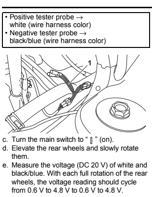
The voltage can be read through a multimeter across the corresponding pins. The voltage as described in the procedure shifted from 0.6 V to 4.8 V twice for one rotation of the rear wheels.
The analog signal has to be converted to digital signal, and then it has to be fed to the computer in terms of number of pulses given by the speed sensor that is set for a desired frequency. The voltage is based on the position of the shaft linked with the rear wheel shaft, rather than the speed. The number of counts of a voltage within a given time can be used to compute the rpm of the vehicle. This speed is used as a feedback measure to reach a desired speed given out by the autonomous system, by controlling the throttle valve.

Test harness

ECU
Computing The Speed Of The Vehicle During Motion
As the wheels are rotated, there are rectangular waveform pulses generated continuously about the test harness. The voltage shift between 0V and 0.7V for a fixed number of times in one rotation of the wheel.
Used an ESP32 circuit that was setup with an arduino code that can count the number of these pulses. It sends a serial data ( frequency - Number of pulses in a second ) by taking the test harness voltage as input through a comparator circuit.
I wrote a ROS node to read the serial data sent by the arduino with corresponding libraries.
Serial library installed from GitHub - github.com/wjwwood/serial
A test was run to count the number of pulses in ROS framework by modifying the code to cumulatively find the total pulses. For a distance of 10m, the number of pulses generated was counted multiple times and averaged. Thus for one rotation of the wheel, the number of pulses was computed. Calculating the circumference of the wheel (Distance moved in one rotation), we can find the number of pulses generated in 1m distance covered by the vehicle. Radius of the wheel is 0.34 meters.
Testing Video At Gascola Test Site
Speed given out in meters per second under a ROS topic as ROS messages.
Implementing A Pid Control Technique - Throttle Controller
Installed the ROS PID package (http://wiki.ros.org/pid) and changed the code by subscribing to topics 'Current speed' computed using the ESP32 microcontroller and 'Target speed' that is given by the planner between waypoints - Meshnav after computing a global plan. A pure pursuit controller is used to traverse between the waypoints.
PID acts about the error between the current and target speed. Tuned the controller to have a PI based throttle control. The response had a very less steady state error due to the Integral term. The anti-windup was also implemented to saturate. The testing video of the throttle controller is attached below.