
"Autonomous Quadcopter Perching using PID control and Ballistic methods"
'Crazyflie 2.0'
Carnegie Mellon University, USA
(October - December 2018)
Applications For Quadcopter Perching
1. Quick emergency landing at high altitudes
--Preserve battery life
--Safely avoid gusty wind conditions
2. Charge at vertical power stations
--More space efficient
--Can stack drones on racks
--Solar charging at tree canopy
3. For exploration and long distance trips
Objectives
1. Detect the wall, start perching phase ✓
--Use Optitrack for surface detection and state estimation
2. Enable perching behavior in CrazyFlie ✓
--Variable angle of surface - 0 deg to 90 deg
--Extreme Pitch/Roll control of drone, nonlinear dynamics
3. Rest on the wall for a certain time ✓
--Use velcro as perching aid
Crazyflie Quadcopter And Landing Pad Used For Perching Problem


FIRMWARE MODIFICATIONS
Modified the maximum roll and pitch angle for the Crazyflie in the firmware and flashed it using Crazyflie client. This is to make large angle of attack feasible, most important feature for perching. Changed the rpLimit variable shown in the following image from 20 to 90, and flashed it to the Crazyflie board.

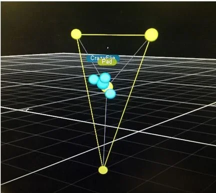
OPTITRACK INTEGRATION
The Quadcopter and the landing pad we used to land the Quadcopter were tracked using optitrack balls in Motive system. It was integrated with ROS to receive messages of coordinates (centroids) of both quadcopter and the landing pad. Streaming rate - 100 Hz.
A screenshot from Motive Optitrack system tracking quadcopter and landing pad :
HOVER CONTROLLER
Now that we had the optitrack integrated with landing pad and quadrotor, we designed a basic hover controller to use it later to track waypoints and reach near the landing pad to initiate perching action. We tuned a PID and wrote a controller node in ROS for the same. We got the following parameters after tuning to get a stable hover controller.
Input to PID: state errors
Output from PID: linear velocities in x,y,z

POINT TO POINT STATE FEEDBACK
By now, we had PID based hover control and optitrack integration was successfully done. Tested if Quadcopter can detect the location of the landing pad using optitrack and reach its coordinates. The quadcopter was expected to reach the given desired location (Landing pad centroid coordinates that the optitrack gives out as ROS messages) from the Quadcopter's position in the space. It successfully reached the landing pad but this was only point to point state feedback and not perching action as such (Fails at 90 degrees). So we then started designing global planner to give set of waypoints for it to travel before it can perch, and also designed a perching controller.
GLOBAL PLANNER - WAYPOINTS
Waypoint 1 - we attempt to reach the waypoint that is vertically above the starting point (from Waypoint 0). The height of this first point is determined as the lowest provably safe height. We define the safe height as 0.5 meters higher than the initial elevation of the quadcopter or the landing pad centroid Z coordinate, whichever is larger.

Waypoint 2 - The second waypoint keeps the same height as the pre-vious waypoint, but moves to above the position we plan to perch from. The (x, y) coordinate of this waypoint corresponds to the (x, y) coordinates of the landing pad with an added offset of 0.5m along the normal vector of the landing pad. These coordinates are calculated below
Taking LN = 0.5 as normal vector length,
[Nx,Ny,Nz] as normal vector of a pad plane,
and [Px,Py,Pz] as landing pad coordinates.
The coefficient sgn(Nz) is included to ensure that the normal
vector is always facing positive z direction.

Waypoint 3 - The third waypoint is where we can initiate the perching action. The (x, y) coordinates of this waypoint as the same as the previous waypoint. As we need ballistic perching (perching control strategy used later), the Z coordinate is adjusted to ensure the ballistic motion will reach the pad. In the equation below Z offset is this conditional offset.

Waypoint 4 - This waypoint is the coordinates of the landing pad P (centroid) that we aim to perch on.
PERCHING CONTROLLER
For landing pad angles greater than 45 degrees, the following control design was adopted.
1. Maximum linear velocity towards the pad until the quadcopter reaches a certain angle or the max time reaches
2. Reverse the direction of velocity command to orient the quadcopter along the pad’s surface. The quadcopter still travels in the same direction due to inertia from step 1.
3. Once we detect that the quadcopter has changed direction, we give full velocity for the quadcopter downwards, which makes it land on the surface.
This is a ballistic operation.
We simply bang towards the pad and reverse the direction when it gets close. We have chosen our waypoints in such a way that it lands on the pad at different angle of landing pad.
PERCHING IN ACTION (<45 DEGREES LANDING PAD ANGLE)
For <45 degree landing pad angle, No ballistic perching motion as described in the previous section is required. Just PID control between waypoints works fine. For landing pad angle > 45°, we require ballistic perching. This has been decided based on observation of the system practically and how it responds.
PERCHING ACTION (>45 DEGREES LANDING PAD ANGLE)
The videos attached here shows how our perching controller performed for >45 landing pad angle.
QUADCOPTER PERCHING (ALMOST 90 DEGREE LANDING PAD ANGLE)
ISSUES FACED
Sometimes the Crazyradio fails to communicate with Quadcopter and there is a sudden drop of the quadcopter during navigation.
Battery charge affects the performance by a huge margin.
Cannot break velcro adhesion for takeoff.
RESULTS
Matched with simulations ? - Yes!
Able to track nearby landing surfaces? - Yes!
Able to perch through entire range of angles? - Yes!
Able to take off after perching? - No! Velcro issues.
Robust hover/navigation controller? PID - Yes!