
“Alternate Driving Mechanism for a
Lever Propelled Wheelchair"
Advisor - Prof. T. Ramesh
Project under Designers Consortium club of NIT-Trichy
Won the second place in Sangam'16 - Project Exhibition
Published a paper in International Journal of Mechanisms and Robotic Systems - InderScience Publishers
(The wheelchair and mechanism has been designed, built, assembled by the team from scratch)
"IDEATION AND PURPOSE
Design, analysis and building a working prototype of a mechanism for a wheelchair which is propelled using the lever with our hands. The mechanism is placed on both sides of the wheelchair and is actuated independently with a lever on each side. The lever which is pivoted about an axis to the sides with help of bearing has to be pushed and pulled continuously to propel the wheelchair. Two sprockets and the lever of the mechanism are constrained to rotate together mounted over a bearing attached to the frame of the wheelchair on both sides. These two sprockets are each meshed with a freewheel which is coaxially placed with the axis of rotation of wheels of the wheelchair through cycle chains. One of the sprocket and freewheel on both sides is meshed in cross-over chain configuration. This enables the wheelchair to propel forward in both push and pull strokes of the lever.
Design considerations and assembly
The main considerations taken into account while designing the mechanism for the wheelchair are:
• propelling the wheelchair forward in both push and pull strokes of the lever
• travel relatively long distances for the same energy input given by the user
• the mechanism using only bicycle components
• simple assembly
• affordable and easily repairable at bicycle shops.
We rotate the lever till a particular angle back and forth which is pivoted about an axis and is mounted on a bearing giving it a push and pull kind of motion. The power given to the lever should be transmitted to the wheels. So, we attach two sprocket coaxially with the pivot point of the lever and thus when the lever is given a to and fro motion, the sprockets along with the lever rotate together with same angular velocity.
Two freewheels are attached on each wheel, present on either side of the wheel and are each meshed with the sprocket through cycle chain (Figure 1). Both the freewheels support the motion in the forward direction and freely rotates in the opposite direction. Thus, there are two cycle chains in the mechanism on each side of the wheelchair (Figure 2). One of these chains on both sides of the wheelchair is in crossed-over configuration.
This crossed-over chain helps us to achieve the forward motion of the wheelchair when we pull the lever backward (backward rotation). The other chain is similar to bicycle configuration, supporting a motion for the wheelchair in the push stroke (forward rotation) of the lever.

Working of the mechanism
When the lever is pushed forward (push stroke), the sprocket and the freewheel that is meshed with crossed-over chain configuration does not provide any output to the wheel, as the freewheel rotates freely in reverse direction (Figure 1). Here, the direction of freewheel rotation is changed due to the crossed-over configuration of bicycle chain. But, the sprocket meshed with the freewheel without crossed-over chain configuration provide an output to the wheels, similar to a bicycle system and thus making the wheelchair move forward. If the lever is pushed backward (pull stroke), then the sprocket meshed with the freewheel without crossed-over chain configuration does not provide an output to the wheels in backward rotation of the lever, similar to bicycle system. But the sprocket and freewheel meshed with crossed-over chain configuration provides an output making the wheelchair move forward, as the freewheel supports the motion in the direction. Thus, we see that in both the push and pull stroke of the lever, we get an output at the wheels and the wheelchair moves forward throughout the motion of the lever in any direction.
Performance Calculation
The performance of the wheelchair is compared with other wheelchairs with respect to the attainable velocity at peak efficiency power output. The velocity of the wheelchair is calculated by the following equation:
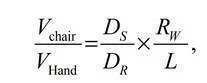
Vchair is the velocity of the wheelchair, Vhand is the velocity of the hand. The Ds and Dr are the diameters of the sprocket and the freewheel, respectively. L is the distance between the point where the user holds the lever and it is the pivot. Rw is the radius of the wheels of the wheelchair.
The sprocket and freewheel have 44 and 18 tooths, respectively, of the bicycle component. Rw = 32 cm, VHand = 0.38 m/s. The least distance from the point of the pivot where we can hold the lever is 14 cm below which our hands might get in contact with the chains meshed with the sprocket. We get Vchair = 2.12 m/s. Available upper body pushing power for propulsion was determined by adapting results from Curtis et al. (1999), and was calculated to be 19.6 W with a pushing force of 58 N and hand velocity of 0.58 m/s.
With the following equation, we verify if the power due to drag, rolling and gravity for the obtained velocity of the wheelchair can be applied by humans.

Values used in this equation, drag coefficient Cd = 1, air ρ = 1.2 kg / m^3 , A = 0.6 m^2, rider + chair mass m = 75 kg, and g = 9.8 m/s^2. Rolling friction coefficient is taken as roll μ = 0.01 for tarmac surfaces and θ = 0 for leveled surfaces. We get Phuman as 19.02 W which is lesser than the power that can be applied by humans, that is 19.6 W. Thus, the velocity attained by the wheelchair is 2.12 m/s.

A proof of concept prototype was constructed to affirm the concept (Figure 3). Bicycle wheels were used for the wheelchair. A bicycle bearing was attached to the frame of the wheelchair on both sides. Two sprockets were welded with each other for them to rotate together. This assembly was then mounted in the bearing. The lever is attached to the crank of the sprocket.
Results and Discussion
Three students from NIT-Trichy were asked to ride the wheelchair over a straight path of length 100 m. And the time taken by the user to travel the distance was calculated using a timer. The average velocity of the wheelchair is calculated by taking the ratio of the distance to the time. The average time was calculated as 47.85 s. The velocity of the wheelchair derived from the calculated time is 2.09 m/s which differs from the theoretical velocity result of 2.12 m/s with an error of 1.42%
The wheelchair propels forward for any change in the position of the lever provided through our hands. Hence, a smaller angle of rotation can be given the front and back to the lever for the same output, but the frequency of push and pull strokes should be increased for the same.
Crossed over chain can be used on either of the two sprockets on each side of the mechanism. The lever acts as a gear. The higher we hold the lever with our hands, the longer is the distance of the point of application of force from it is pivoted axis over the bearing. Hence, there is more torque input and this functions as a low gear. If we hold the lever at a lower level with our hands, then there is less torque input and this functions as a high gear.