
S2E6: How do Segways self-balance?
Introduction
The first time I saw a Segway was at the movies. But what caught my attention, even more, was the unicycle! I have driven electric scooters for work but I never tried riding these vehicles. So I recently got a Unicycle to explore how it works and understand the Segway technology from the Patent files.

Figure 1: Unicycle (left) and a Segway (right)
But before we jump in, what is so unique about these vehicles? Let’s take the example of a bicycle. When you’re riding a bicycle, you actively make efforts and use your legs to balance once you come to a stop. This isn’t the case in a Segway at rest - the controller self-balances the vehicle, so you don’t need to place your legs on the ground. And in a unicycle, you need to balance with your legs at rest but all you need to do to ride the vehicle is to use lean in the direction you want to move. But how are they made possible?
Here is how! The balancing controller discussed here for a Segway applies to a Unicycle as well.
#1: Reaction Torques

Figure 2: Reaction Torques
Let’s say we have a simple model of a long vertical handlebar with a wheel that can rotate about its center O. Now if we apply a Torque Tw to the wheels, there is a reaction torque on the vehicle in the opposite direction equal in magnitude. To digest this fact more easily, you can draw similarities to Newton’s Third Law of Motion - Every force has an equal and opposite reaction.
#2: How does a Segway self-balance the rider standing on the Segway?
To use a Segway for commuting, a rider steps on it and leans forward to go ahead. To apply brakes or go in the reverse direction, you can lean backward accordingly. But how does the Segway balance the rider and move ahead at the same time? Picture the following to get a general idea. We’ll look at the exact control technique in the next section.
Imagine trying to balance an upright bottle with one finger for a moment to understand this fully. In the example of balancing a bottle with only one finger, you move your hands along the direction the bottle is falling. The idea used in a Segway is the same!
When you lean forward on a Segway-like machine, you are applying torque to the handlebar, making it rotate clockwise. Now we want to counteract and apply a torque in the anticlockwise direction so that the user does not fall face first.
We just saw in the earlier section that rotating the wheels clockwise applies a reaction torque on the handlebar in the anti-clockwise direction. This is exactly what we want. So in an attempt to balance the rider, the wheels move forward to counteract the torque.
You can never lean forward or backward and fall when the Segway is active. The motors are very reactive and always catch up before significant deviation in the pitch angle theta (angle from the vertical).
But how do we control and apply the right amount of Torque to make this happen? What if the motor overreacts and pushes you making you fall backward? Let’s see how this is handled.
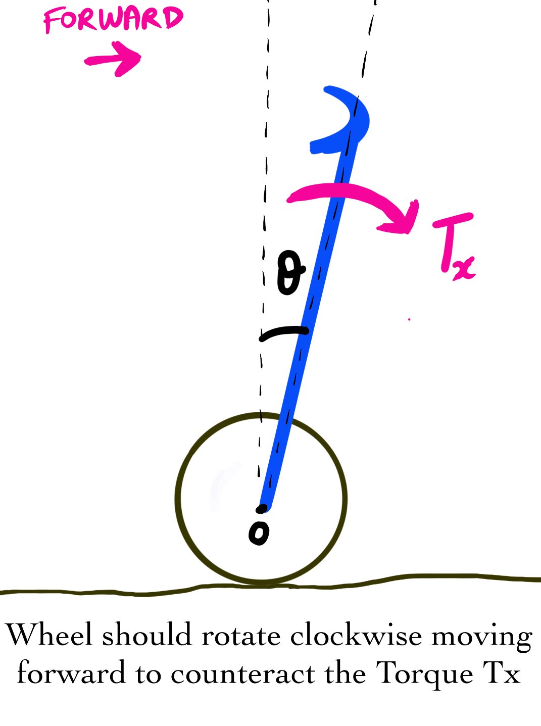
Figure 3: Control ideology for a Segway
#3: How to compute and apply the right amount of Torque?
The Segway has gyroscopic sensors that can determine the user's lean (orientation angle theta with the vertical, aka pitch). The larger the theta, the more torque is applied to the wheels using a PID algorithm to correct for the lean and stabilize the Segway. We briefly reviewed the PID algorithm in my Newsletter issue on Adaptive Cruise Control. I’m attaching a link to the YouTube video again if you’d like to read about it. It basically works like your thermostat maintaining the temperature of your room.
Each motor for the wheels has a sensor to measure the position or angular velocity of the motor shaft. A hall sensor is used to sense the position of the rotating shaft. An advantage of the hall sensor is its low cost.
Motor Command = Kp(theta) + Kd(thetadot) Where Kp and Kd are gains - constant numeric values. Theta is the pitch angle and thetadot is the rate of change of pitch. This voltage generates torque to the wheels of the Segway. The motors are all brushless DC.
In this example, I’ve taken the desired theta as 0 (vertical position of the handlebar) and desired theta dot as also 0 as we don’t want the pitch angle to vary with time. This correction algorithm runs 100 times a second.
A different control technique called LQR can also be applied for the same. I’ll leave it to you to explore this further as it’s a ton of Math unrelated to the objective of this blog post. You can find projects that I’ve done in the past using the same on my website.
#4: How does the Segway go over an Obstacle with complete balance and not stop!?
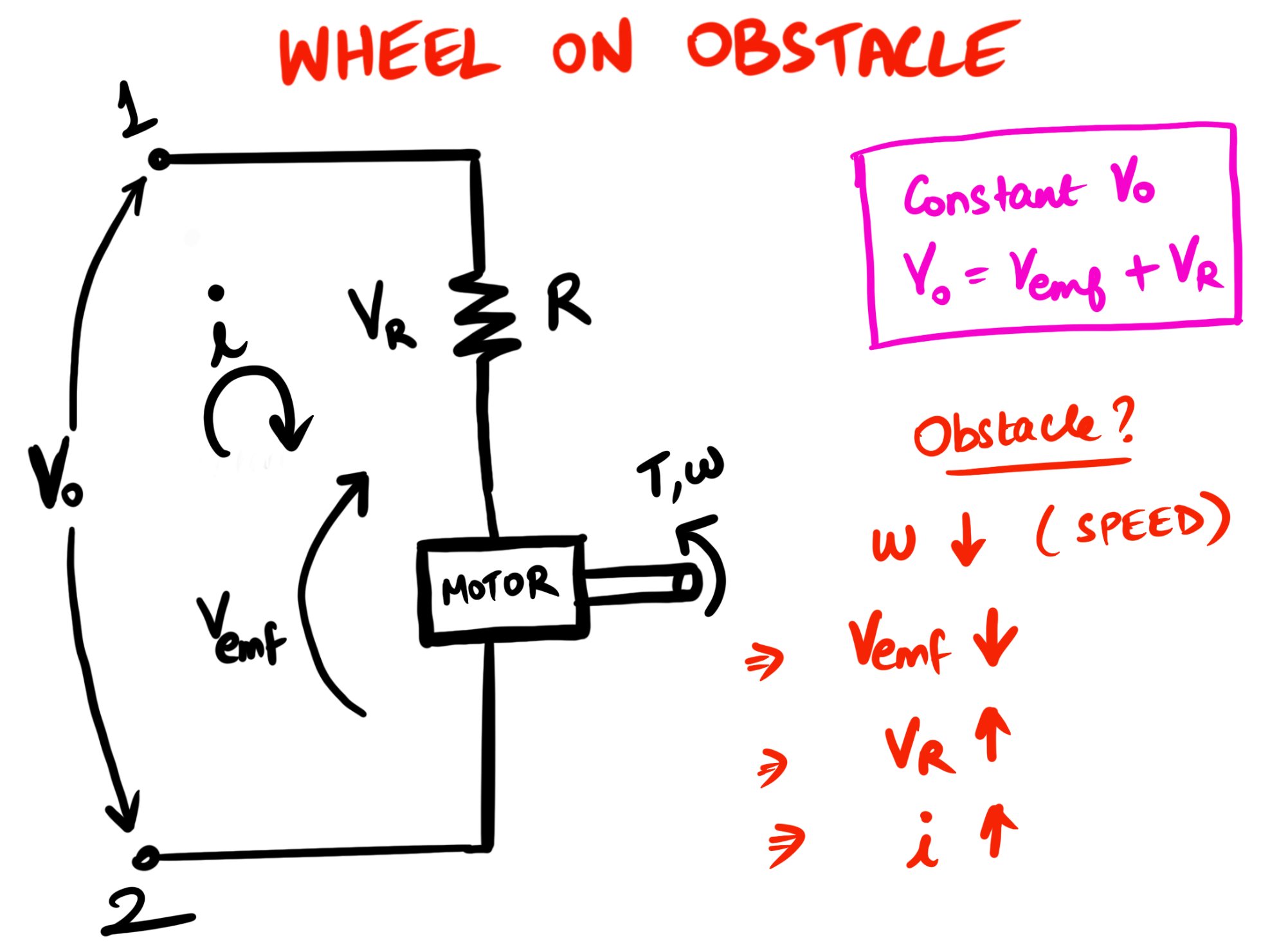
Figure 4: Motor Model for the Wheels
The Segway controller applies a Torque when we lean forward or backward - We just saw the controller algorithm that it’s only based on the pitch angle. But what if the Segway has to go over an obstacle? In this scenario, can there be a case where the Torque applied to the wheels to counteract the lean angle is not sufficient to get over the obstacle? Let’s see!
A constant voltage Vo is applied across terminals 1 and 2 of the motor as shown. And a resistor R and a rotating motor shaft for the wheels are connected in series.
Now, let’s say that the Segway hits an obstacle like a speed breaker and has to go over it. The angular velocity (w) of the rotating motor shaft (wheels of the Segway) reduces once it hits the obstacle.
This implies, The voltage across the motor shaft Vemf (Motor Contant Kv * angular velocity ‘w’) also reduces as its directly proportional to ‘w’.
But, as Vo is a constant and if Vemf has reduced, then the voltage Vr across the resistor R should increase to balance the equation.
This means more current is drawn into the circuit (Ohm’s Law V=iR)
As a result, the Torque (T = motor constant Kc * Current I) to the wheels increases.
Thus, the angular velocity of the wheels (’w’) increases as well. This additional speed after the drop makes it possible for the Segway to overcome the obstacle.
All this happens in a fraction of a second. The motor essentially acts as its own feedback sensor!
#5: Turning mechanism in a Segway
The user uses the handlebar of the Segway to perform a turn. Pushing the handlebar to the right makes the Segway take a right turn. Likewise, for the left turn.
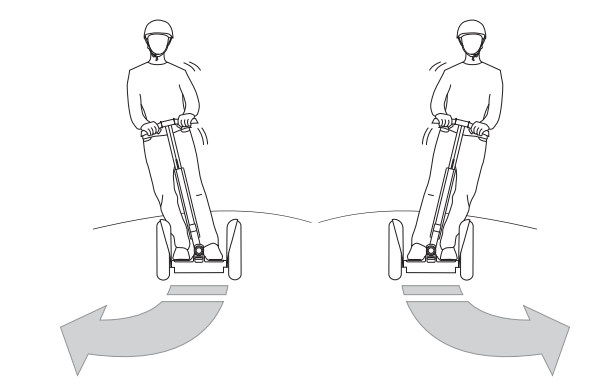
Figure 5: Performing a turn in a Segway (Source: Segway manual)
Stability: When you are making a right turn in your car, you get pushed towards the left due to centrifugal force. This is advantageous in the case of a Segway, as we lean towards the right for a right turn and the centrifugal push us to the left, it gives us stability from not falling.
The more the angle of the handlebar, the more aggressive the turn (shorter radius). One can also turn in place by leaning accordingly.
But how is simply leaning to the sides converted into a turn? Segway has a load cell mounted close to the pivot of the handlebar at the bottom. A load cell is a sensor that basically converts a force such as tension, or compression into an electrical signal. It is a force transducer. As the force applied to the load cell increases, the electrical signal changes proportionally based on the PID algorithm - which implies a more aggressive turn. A strain gauge is an example of a Load cell.
We need to command the motor with a balancing Torque we saw in the previous section. But now, we need to apply a Yaw command as well, for performing the turn. How do we combine both? (Perform a turn while also maintaining stability) Based on the direction of the handlebar motion, the left and right wheels are commanded as follows - Let’s take the example of a right turn.
MotorCmdLeft = BalanceCmd + YawCmd
MotorCmdRight = BalanceCmd - YawCmdHere, each command is basically a voltage given to the left and right motor amplifiers.
BalanceCmd is the command sent by the controller to each motor amplifier to maintain the Segway in a balanced state while moving or at rest.
YawCmd is based on load sensor reading with direction. In this case, it increases the command to the left wheel, while decreasing the command to the right wheel. Thereby causing the Segway to execute a right turn.Note that the left wheel has to rotate faster than the right wheel to make a right turn. Which is exactly what we’re doing here.
Conclusion
If a component failure is detected, a deceleration-to-zero routine is executed by the controller to automatically bring the transporter to a stop. The Segway does not require a break, because the controller controls the position of the wheel directly. If you wish to stop, lean in the opposite direction to the direction of the moving Segway.
Reference: US 6538411 B1, 6651766 B2
Thank you for taking the time to read my blog post. If you liked what you read, consider subscribing to my newsletter for exclusive content and understand how a gadget works in only 3 minutes, sent directly to your inbox every Wednesday. We'd love to have you as a part of our community. Also, if you found this post to be informative or enjoyable, please share this with your friends on social media. Thank you!